
In the vast and profound ocean, the stable operation of critical systems—whether remotely operated vehicles (ROVs) for deep-sea exploration, dynamic cables connecting offshore wind farms, or surface monitoring buoys—relies on one seemingly inconspicuous yet essential component: the buoyancy module. Much like "invisible wings" for underwater systems, buoyancy modules enable equipment to overcome gravity, maintain proper attitude, and reduce mechanical tension.
This article provides a systematic analysis of buoyancy modules, covering their working principles, core materials, design considerations, typical applications, and common failure modes. It aims to help engineering professionals gain a deeper understanding of this fundamental yet crucial technology in marine engineering.
1. Buoyancy Principle
The design of buoyancy modules is rooted in the classical principle formulated over two millennia ago by the ancient Greek scientist Archimedes: The buoyant force acting on an object immersed in a fluid is equal to the weight of the fluid displaced by the object.
In marine engineering, this principle is precisely quantified as: Net Buoyancy = Displaced Volume × Seawater Density – Module Self-Weight
For example, a buoyancy module with a volume of 1 m³ operating in seawater (density ≈ 1025 kg/m³) theoretically generates approximately 1025 kg of buoyant force. If the module itself weighs 200 kg, its net buoyancy is 825 kg, which can be used to support other equipment or counteract cable tension.
However, real ocean environments are far more complex than idealized models. Deep-sea pressure, long-term immersion, and bio-fouling all affect buoyancy performance. Therefore, practical designs must account for safety factors, long-term performance degradation, and environmental loads.
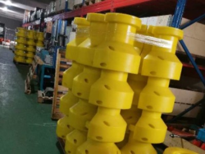
2. Core Materials: From Conventional Foam to Syntactic Foam
The performance of a buoyancy module hinges on its material selection. Traditional closed-cell foams (e.g., polyurethane or polyethylene) are cost-effective but prone to compression and water absorption under deepwater conditions. Modern deep-sea applications widely use syntactic foam.
2.1 What is Syntactic Foam?
Syntactic means structured, referring to a composite material composed of a high-strength resin matrix (such as epoxy or vinyl ester) filled with microscopic hollow glass microspheres (HGMs). These microspheres act like countless miniature pressure vessels, effectively resisting hydrostatic pressure at depth.
2.2 Material Advantages:
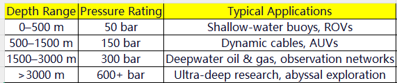
High Pressure Resistance: Capable of withstanding static pressures at depths from 500 m to over 6,000 m
Low Density: Typically 0.4–0.7 g/cm³, enabling high net buoyancy
Low Water Absorption: <0.2% after 24-hour immersion, ensuring long-term stability
High Compressive Strength: Exceeding 100 MPa, suitable for load-bearing structural integration
2.3 Pressure Rating Classification (Common):
2.4 Relationship Between Density and Compression
As depth increases, the material compresses, reducing volume and displaced water, thereby decreasing buoyancy. High-quality syntactic foams maintain volume compression below 5% at 300 bar, whereas inferior materials may exceed 15%, leading to significant net buoyancy loss.
3. Typical Applications: Where Buoyancy Modules Excel
Buoyancy modules are not off-the-shelf products but are customized system components tailored to specific mission requirements. Here are three primary application areas:
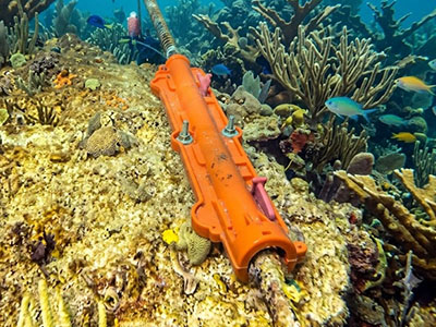
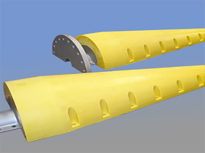
3.1 ROV/AUV Buoyancy Units
Remotely operated or autonomous underwater vehicles require precise neutral or slightly positive buoyancy to minimize propulsion energy consumption. Buoyancy modules are typically mounted externally, providing stable lift, with modular designs allowing for center-of-gravity adjustment.
Requirements: Lightweight, impact-resistant, easy to install
Example: A deep-sea ROV operating at 3,000 m relies on eight syntactic foam modules to generate approximately 600 kg of net buoyancy, enabling extended inspection missions.
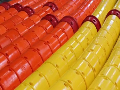
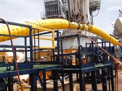
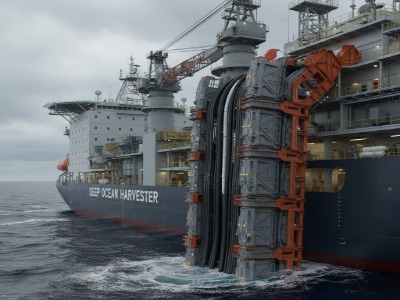
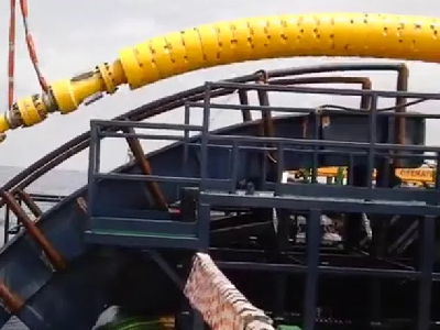
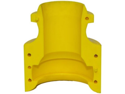
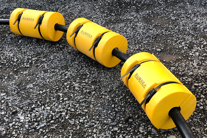
3.2 Buoyancy Sections for Dynamic Cables
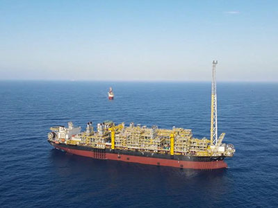
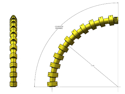
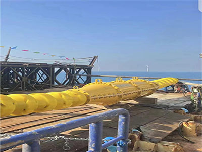
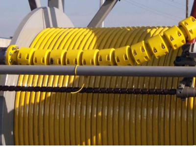
In floating offshore wind farms or FPSOs (Floating Production Storage and Offloading units), power or umbilical cables extend from the seabed to a floating platform and are subject to significant wave- and platform-induced motion. Installing buoyancy modules along the cable midspan creates a "lazy-S" or buoyant span, dramatically reducing cable tension and bending stress.
Design Considerations:
Buoyancy distribution must be uniform to avoid localized high stress
Modules must be flexible to accommodate cable bending
Outer layers often include abrasion-resistant jackets (e.g., UHMWPE)
Benefits: Can reduce dynamic cable fatigue damage by over 50% and extend service life by 10+ years.
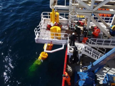
3.3 Buoys and Mooring Systems
Oceanographic buoys, navigation markers, and communication relays rely on buoyancy modules to maintain stable surface positioning. In deepwater mooring systems, buoyancy modules are sometimes used to "lift" anchor chains, reducing seabed friction.
Challenges: Must withstand wave impact, UV degradation, and biofouling
Solutions: Outer layers coated with fiberglass (FRP) or polyurethane to enhance durability
4. Key Design Parameters: Five Critical Metrics Engineers Must Know
Designing a buoyancy module involves much more than simply "adding foam." The following parameters must be carefully evaluated:
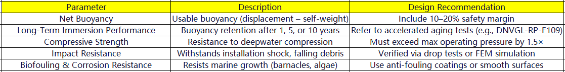
Additionally, Finite Element Analysis (FEA) should be performed to simulate stress distribution under compression, bending, and impact, ensuring structural integrity.
5. Common Failure Modes: Why Buoyancy Modules Fail
Despite advances in material technology, buoyancy modules can still fail in practice. Key failure mechanisms include:
5.1 Foam Cracking
Cause: High material brittleness, installation impact, rapid temperature changes
Consequence: Cracks allow water ingress, reducing buoyancy
Prevention: Use toughened resins, avoid sharp corners, control curing process
5.2 Water Ingress
Cause: Broken microspheres, microcracks in matrix, poor sealing
Consequence: Increased density, reduced net buoyancy, potential sinking
Detection: Regular weighing, X-ray inspection, buoyancy test tanks
5.3 Debonding
Cause: Poor adhesion between foam and metal core or outer jacket
Consequence: Module detachment or localized overstress
Prevention: Surface treatment (e.g., sandblasting, plasma), use of structural adhesives (e.g., epoxy)
5.4 Biofouling and Marine Growth
Long-term effect: Adds weight and alters hydrodynamic behavior
Countermeasures: Scheduled maintenance, anti-fouling paints, easy-to-clean surface design
Conclusion
A buoyancy module is far more than just a piece of foam—it is the foundation of safe and reliable deep-sea operations, and a key factor in balancing system performance and economic efficiency. In high-stakes applications such as offshore wind, oil & gas, ocean monitoring, and underwater robotics, selecting the right buoyancy technology is equivalent to safeguarding your entire project.
As a leading provider of high-performance subsea buoyancy modules, we offer a complete range of deepwater-grade syntactic foam modules, rated for depths from 500 to 6,000 meters. Our modules are fully customizable in size, shape, and integration structure to meet your exact engineering needs.
If you're seeking a reliable solution for dynamic cable tension reduction, ROV buoyancy balancing, or long-term buoy stability, contact us today! Our engineering team is ready to support your next marine challenge with proven, certified, and field-tested buoyancy technology.
You can contact us any way that is convenient for you. We are available 24/7 via email. You can also use a quick contact form below or visit our website. We would be happy to answer your questions.